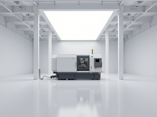
From Selection to Production: A Five-Step Implementation Process for the XK7145 Vertical Knee-Type Milling Machine
The XK7145 is a vertical knee-type milling machine designed for heavy-duty cutting, with a long table longitudinal travel and a thickened column. Combined with hardened rectangular guideways, it performs high-stock-removal face, step, groove, and end milling on steel and cast iron workpieces. The five steps below follow the actual shop-floor implementation sequence, helping procurement and process engineers align quickly across machine selection, installation, and production ramp-up.
Step 1: Evaluate the Workpiece and Machining Allowance
Begin by reviewing the material, maximum outline dimensions, and single-side machining allowance of the parts to be machined, then determine the required spindle power, table load capacity, and travel range. Parts with large allowances and high material hardness should use a heavy-duty structure first, to avoid precision degradation caused by small machines running at full load for extended periods.
- Whether the maximum workpiece outline and fixturing method exceed the table surface and the longitudinal/lateral travel
- Material grade and hardness; rough milling single-side allowance is typically controlled at 3–6 mm
- Batch profile: single-piece and small-batch work is better suited to a machine that combines general-purpose vertical milling with CNC capability
- Whether CNC axes will be added later, reserving expansion space for handwheels and servo interfaces
Step 2: Select the Machine Model and Accessories
Lock in the machine specifications based on the evaluation, and finalize the accessory package supplied with the machine. The XK7145 is available in handwheel-operated and CNC configurations; the former suits workshops with varied processes that rely mainly on manual experience, while the latter suits applications with high consistency requirements for contour and curved-surface batch production. Accessories are best fully equipped in one purchase to avoid repeated procurement later.

Common companion accessories include flat-jaw vises, rotary tables, dividing heads, and tool chuck sets. When specifying options, check that the table T-slot specifications match the accessory mounting dimensions, ensuring no displacement occurs under heavy-duty clamping.
Step 3: Installation and Alignment
Before the machine is set in place, confirm that the foundation is level and meets load-bearing requirements. Once the anchor bolts are secured, level the table in both directions, then recheck the perpendicularity of the spindle axis to the table. After alignment is complete, lock the gibs and clamping plates to reduce micro-displacement during machining.
- Use a frame level to level the table in both directions, keeping the error within 0.02/1000
- Recheck the radial runout and face runout of the spindle taper bore
- After confirming that the electrical connection meets on-site voltage and grounding requirements, run the machine without load for a trial run
Step 4: Trial Cutting and Acceptance
Perform trial cutting with blanks identical or similar to those used in actual production, focusing on surface roughness, dimensional consistency, and machine vibration. Acceptance should cover both static geometric accuracy and dynamic performance under cutting conditions, with records retained for later traceability.
| Acceptance Item | Method | Reference Requirement |
|---|
| Table flatness | Feeler gauge / straightedge inspection | No noticeable gap over the full travel |
| Spindle radial runout | Dial indicator measurement | Meets factory accuracy requirements |
| Trial-cut surface roughness | Finish-mill a sample with identical parameters | Meets drawing specifications |
| Vibration under heavy load | Observe during high-stock-removal rough milling | No abnormal chatter or stalling |
Step 5: Batch Production
After trial cutting passes, freeze the cutting parameters and fixturing plan and move into batch production. It is recommended to document the tooling, spindle speed, feed, and fixturing datum of the first article into a process card, and to sample-check key dimensions at fixed intervals during the batch to ensure lot-to-lot consistency. Under continuous heavy-duty conditions, the machine should be inspected periodically for guideway lubrication and gib clearance; timely maintenance extends precision life.

Should additional capacity be needed later, a second machine of the same specification can be added on the same process datum to reduce setup time and enable flexible order switching.